
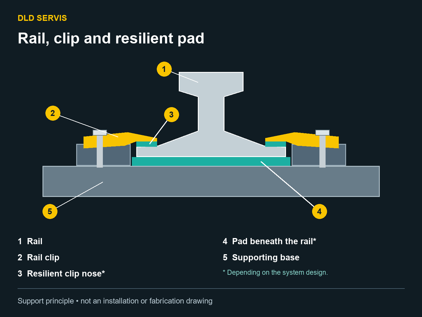
A clip comes loose, the rail shifts, and tightening the bolts only solves the problem briefly. Choosing a “stronger bolt” is not enough. The whole assembly needs checking: the rail, clip, clip base, rail support and runway geometry. Adjustable rail clips allow the rail position to be corrected, but only within the capabilities of the particular system.
What a rail clip adjusts
An adjustable fixing allows lateral alignment of the rail relative to its support. The clip design determines how it adjusts, its available range and what rail movement remains permissible. Not every clip is intended to clamp the rail completely rigidly: some assemblies allow controlled movement. The documentation for the support system governs this.
Lateral adjustment is not vertical levelling. A clip cannot repair a deflected girder, a damaged rail or an unsuitable support. Before realignment, the measured geometry must be understood and the proposed position checked for unacceptable eccentricity relative to the supporting structure.
Different rails need compatible assemblies
A bolt designation or similar appearance is not enough for selection. Rail foot width, thickness and shape matter, together with the clip contact position, its base and the load path into the support. Selection must also account for loading and the required adjustment range.
There is no simple rule that one rail profile has only one suitable clip. Several systems may suit the same rail. Conversely, a clip that appears to fit dimensionally may still be unsuitable for the assembly. Compatibility must cover the whole arrangement, including any rail pad.
When a rubber pad is useful
A resilient pad beneath the rail foot forms part of the support. In a suitably designed assembly it can reduce concentrated contact loading and help limit noise and vibration. Adding a pad is not automatically an improvement for every runway.
Systems exist both with and without pads. The system design determines their use; replacement requires checking the specified material, thickness, stiffness and service conditions. An arbitrary strip of rubber is not an equivalent replacement. Adding a pad changes the rail height and the relative position of the foot and clip, so it cannot be assessed separately from the fixings.
A pad under the rail and an elastic element in the clip are different components. Where a clip has a resilient nose bearing on the rail foot, that element has its own role in the assembly. Its presence alone does not determine whether a pad is also needed underneath the rail.
Example: a new rail with the old clips
A planned replacement changes the rail profile and introduces a pad. The existing bolts still fit the holes. This does not establish that the fixing is suitable: contact with the new rail foot, assembly height, available adjustment and component capacity all need checking. This is an illustrative example, not a description of a customer project.
Information to prepare for assessment and service
- The rail designation and an available profile drawing.
- Photographs and identification of clips, bases and anchoring arrangements.
- Whether a pad is present, its specification and condition.
- Runway and crane documentation, survey results and observed operating symptoms.
- Safe access and shutdown arrangements.
Repeated loosening calls for investigation rather than repeated tightening alone. After work, geometry and fixings should be checked to suit the intervention and documentation. This article cannot supply a universal tightening torque, clip spacing or tolerance. A competent team must plan and carry out the work, securing the equipment against movement and unintended start-up.
DLD Servis provides crane runway surveys, realignment and repairs. For an initial assessment, send the rail designation, photographs of the fixings and a description of the problem. Crane runway service and realignment.
Sources and scope
SCI P178 (1997), section 6.6, explains support and fixing principles; its historical standard references are not presented here as current requirements. The official ISO 12488-1:2012 catalogue covers geometrical tolerances for wheels and tracks; applicable values require the relevant documentation and assessment. HSE provides UK maintenance safety guidance, not local legislation for other countries. Sources checked on 19 October 2026. This article and diagram do not replace system-specific design or installation instructions.